Paco – DER-2000 Automatic Voltage Regulator Repair
Paco – DER-2000 Automatic Voltage Regulator Repair
By Jestine Yong on May 8, 2015

There is a place in the city I live, where one can find used electronic equipment, either domestic or industrial, at really very low prices. Sometimes these devices, if one is lucky, work perfectly and need only a good cleaning. I never understood why they were thrown away as garbage!! Anyway in most cases they need to be repaired.
Last week I, along with my close friend George, visited the place for “hunting down” anything interesting in order to repair it and then put it in regular use.Well, I found a 2KVA A.C voltage regulator of the so called “tap changer” type. These below are its front and back views (after I cleaned and repaired it).
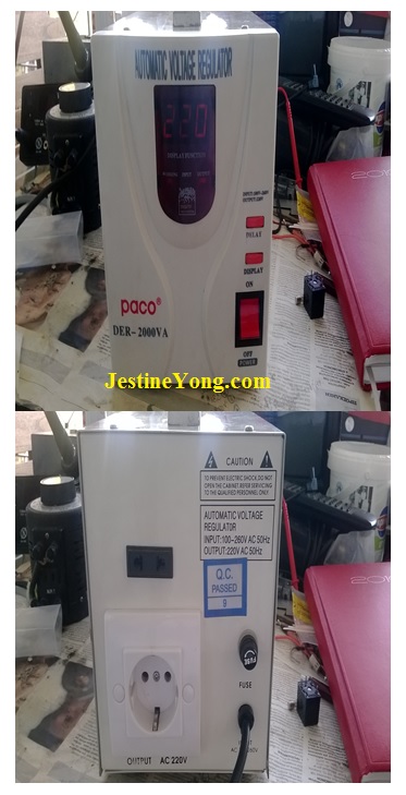
I took the unit at home and tested it to see its operational condition. When powered, the display was normally on. It was not as bright as I would like it to be, but this was due to the chemical changes within the plastic red cover because of aging. When troubleshooting it later on I didn’t find any electrical cause for it. Measuring the voltages across the current dropping resistors and applying the Ohms Law I found the current flows through the LEDs to be at reasonable levels for a normal brightness and within their limits. I also checked the brightness after removing the board from the front cover, without the filtering action of the red cover and it was fine. So, when I saw that the display was normal, I connected the unit to my variac in order to check its switching points (i.e. the tap changing according to the input voltage threshold variation). The first indication was as below.

When varying the input voltage within the operational range of 100-245V of this regulator using my little variac, I noticed that the output voltage was not changing normally and also I could not hear clearly the closing click of one of the four relays of its controller board.
My next step was the installation of a 2mm LED annunciator across each coil of every relay, in order for me to have a visual indication of their activation. So, I measured the coils’ supply voltage which I found to be at 19,5V D.C. This voltage is on purpose higher than the nominal coils’ voltage, rated at 12V D.C. The purpose is to drive satisfactorily the relay moving contact at low input voltages. However voltage/current dropping resistors were also provided, connected in series with the coils, in order to absorb their excess currents when working near or above the nominal input line voltage.
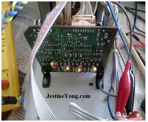
Below you can see these annunciator circuits I installed on the solder side of the controller PCB.
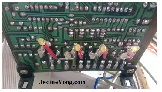
I always install circuits like these when working with relay circuits just in order “to make my life easy”. It is very difficult to tell which relay has a stuck contact and produces weak clicking sound when activated or deactivated. Moreover, the contacts distribute line voltages at the output of the device, one of them being really high around 290V A.C, depending on the input voltage, rendering any related measurements at this level very dangerous. So, it is always better to have a simple visual indication of each relay’s activity and measure the result safely, directly at the output outlet terminals of the regulator.
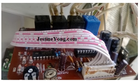
With the aid of the LEDs, I spotted the stuck relay quickly and replaced it. The new one is the blue colored, as shown below.
After a new test, I noticed that there was inconsistency between the voltage display of the regulator, when measuring its input voltage by pressing the DISPLAY button, and my multimeter’s display. In normal operation the regulator’s display shows its output voltage. When this button is pressed, the display toggles momentarily to its input voltage, and then back to its output voltage again.
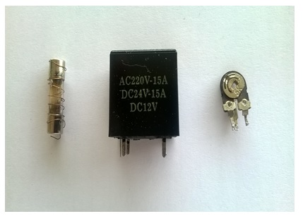
I tried to readjust the switching thresholds (or investigate for any change in behavior) varying the values of the two trimmers shown above, one of them each time and observing the resulting changes. As you can see in the above picture, I already replaced the left trimmer (both had the same shape and same value of 5KOhm) which was open and there was no change when I tried to adjust it. After the replacement and the following adjustment by varying the input voltage, the circuit had healthy behavior.
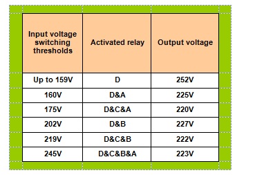
I checked the device throughout its entire dynamic range and its output voltage was within acceptable limits. The tap changing sequence is shown in the table below.
In order for you to decode the information of the above table, please note that the names of the relays are arbitrarily given by me. As regards their location, you are kindly requested to see the photo of the solder side view of the controller PCB (either above, with LEDs “off”, or below, with LEDs “on”). The LEDs are connected in parallel with the relevant relay coils, one per each coil.
D is the one located at the leftmost side. C is at its right side, next follows B and finally A is the replaced one, at the rightmost side of the PCB, the blue one as seen from the components’ side view.
Observing this table, one might ask: “O.K, but what is the use of the D relay as it is always activated” ?
The answer is simple. This relay serves the “DELAY” function, that is, it’s always activated, but only after the delay time expiration. Electrically, it keeps the phase output conductor (L) disconnected during the delay count down time. Therefore the “game” is practically played with the rest three relays.
I also noticed that the displayed values are tricky! When the input voltage is far below the nominal one, the input shows a flashing “L” meaning “low input”. This happens below 160V input level. The trick is when the input voltage approaches 180V. From this level up to 245V input, the display shows permanently 220V output, while in reality this changes starting from 245V (at 180V input) to end up at around 230V at maximum input (above 245V). Note that all the tests to identify the switching points were performed with no load at the regulator’s output because my variac is a very small unit of only 150VA, which I use exclusively for adjustments. Not for load tests. For full load tests of this regulator I would need a 5KVA variac, but I don’t need to own such a “monster” because these tests are not my every day professional tasks and what’s more, this kind of equipment apart from being very specialized, is very expensive as well.
I also tested the DELAY function switch for proper operation and it was functioning properly. In general, when first time powered, the unit counts 6 seconds before connecting the load to its output. Within this time interval, the operator can press the DELAY switch and the unit counts now 120 seconds (or 2 minutes) before connecting the load to its output.
This function is very important for (simple types or, in other words, for non microcontroller operated) refrigerators possibly connected to the regulator’s output. The reason is that if the refrigerator is subject to a power failure when normally running and the power is restored after a few seconds, there is always a possibility for its compressor not to be able to reach its maximum speed due to high hydraulic pressure developed within the relevant network and this creates a domino-like phenomenon to the current draw of the compressor in relation to its temperature, that is, the current gets higher due to the lower than normal speed and as the speed is not increasing this results in increase of its windings’ temperature. The temperature increases in turn their resistance, decreasing even more the compressor’s speed (it may also stall) and it heats up even more as well, increasing more its power consumption…and the story goes on until it finally either develops inter-winding shorts or its windings open completely in their weakest point, rendering it destroyed because of that domino-like acting thermal stress.
The long time delay serves the purpose of letting the hydraulic pressure to drop in order to make things easy for the compressor, helping it to restart normally without being overloaded. And my reference about non microcontroller operating devices has to do with those old and “primitive” designs. Most modern refrigerators and air-conditioners are equipped with sophisticated microcontrollers and relevant protection systems which avert such perils.
So, when I finished with the functional tests, I installed on it two protection circuits. First was the installation of input overvoltage protection circuit consisting of three varistors connected as follows; ground to phase, ground to neutral and phase to neutral. They are all rated at break-over voltage of 300V.
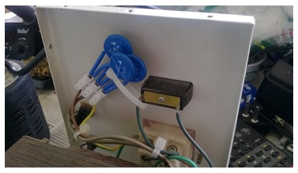
I connected the protection circuit right after the 15A input fuse. So, whatever happens to the device, the fuse will immediately blow and protect the main winding of the (auto)-transformer and the load itself. I also installed an additional R-C snubber circuit right at the output side of the main power switch contacts which feed the transformer in order to protect both the switch contacts from arcing and the output load from overvoltage spikes. You can see this circuit in the photo below. The component values are typical: 100nF/630V for the capacitor and 100Ohm/1W for the resistor.

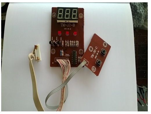
And this below is the overall solder side of both the display and the switch boards.

Below you can see all the LED annunciators glowing, while the input voltage was adjusted to 245V level.
And these below are the component sides of both the display and the switch boards.
Finally I thought to take a look at the fuse holder. There was a surprise waiting for me there. Well, this drives me crazy whenever I see it and my eyes start glazing! The fuse was blown and somebody had put a (fortunately thin but nevertheless dangerous enough) copper strand of soft multi-stranded low power cable around the glass body of the fuse, eliminating thus any chance of the device’s survival under either an unacceptable loading or overvoltage condition which could possibly occur during its operational life!!…
Anyway, the three defective parts I found are shown below.
My friend George had bought the same device two years ago. A few days ago when I visited him, he had the unit staying in his own laboratory at home without even having tested it. As I saw it, I asked him to put it on the bench and test it. George was a colleague of mine in the past and he has the same interest with me in repairs. So I used his bench to check the device and make comparisons with what I had seen with mine. Unfortunately George was not lucky at all! When I powered the unit, there was no display at all, no output and instead there was strong 50Hz hum noise coming from the transformer, clearly heard from a 50cm distance away from the device!
I checked its fuse and the result was really disappointing. The fuse had a thick wire soldered across its ends…Unfortunately I threw it away without taking any picture of it in order to post it, but I guess you can imagine about it…
Then I opened its upper cover to see the rest of the disaster…
You can see below a side view of the autotransformer. Please take a good look at the color of its core…You will clearly see there the remains of the enamel varnish, in light brown color. I cannot imagine what temperature level had this core reached before shorting the coils around it as I finally found.

This below is a top view of the same transformer…No difference from the side view…

Later on I removed the controller board and after that all the relays on it and tested them separately. The version of this PCB was not the same with mine. It uses relays of different shape which can withstand heavier currents than the relays installed in my version. Nevertheless one of them was completely stuck again.
These are shown below. Note again the color of the PCB itself. When I touched any component on it, immediately its solder point pads on the other side were lifted!! Such a toasted PCB I have never seen before in my life!

George was completely disappointed with the sad end of his voltage regulator…But he kept the entire empty case of it in order to enclose some other home-made electronic construction as he usually does. Well, this is also a good habit. Whatever escapes from scrap keeps its value as it can be reused as useful material again, keeping the garbage pile at low level as well…
I hope you enjoyed this repair description as I enjoyed the repair itself!

This article was prepared for you by Paris Azis from Athens-Greece. He is 59 years old and has more than 30 years’ experience in electronics repairs, both in consumer and industrial electronics. He started as a hobbyist at the age of 12 years and ended his professional carrier as a senior electronics technician. He has been a specialist in the entire range of consumer electronics repairs (: valve radio and BW TV receivers, transistorized color CRT TV, audio amps, reel and cassette tape recorders, telephone answering and telefax devices, electric irons, MW cooking devices e.t.c) working in his early stages at the official service departments of National-Panasonic first and JVC afterwards, at their premises in Athens.
Then he joined the telecoms industry, working for 20 years as field supporting technician in the sector of DMRs (: Digital Microwave Radio transmission stations), ending his carrier with this subject. Now he is a hobbyist again!
Please give a support by clicking on the social buttons below. Your feedback on the post is welcome. Please leave it in the comments.
P.S- If you enjoyed reading this, click here to subscribe to my blog (free subscription). That way, you’ll never miss a post. You can also forward this website link to your friends and colleagues-thanks!